Author: Jonathan Hendrickson
Let’s dive a little deeper into motor, propeller, and electronic speed controller (ESC) selection. In particular we will investigate the Turnigy 3536c 1100Kv with several APC Electric propellers and a Turnigy 60amp ESC.
To dive in deeper a couple of tools are needed. We will need a watt/amp meter and a kV/RPM meter with a built-in servo driver, or a separate servo tester can used to command the ESC. We also need to review some definitions, abbreviations and equations:
Prop = Propeller
RPM = Revolutions per Minute
ESC = Electronic Speed Controller
kV = RPM per volt
LiPo = Lithium Polymer battery
Outrunner = type of brushless motor that has the permanent magnets rotating externally around the stationary windings
Inrunner = type of brushless motor that has the permanent magnets rotating internally with the windings surrounding the magnetic core (less magnetic induction due to the absence of iron cores in the stator)
Stator = stationary windings of an outrunner or inrunner motor
Bell = Outer rotating portion of an outrunner motor that the permanent magnets are attached to
Pole = Magnetic pole in a motor
Electromagnetic Induction = Electricity generated by magnetic poles passing (in this case) the stator (like a generator)
EMF = Electromotive force in this case caused by electromagnetic induction
#cell (LiPo) = Battery cells in series 3.7 volts each
(example 3cell=11.1volt battery pack)
##c battery = discharge rate (30c = 30 x Battery capacity in Amps)
2200mAh 3cell 30c LiPo = 66A discharge rate
(30x2.2A=66A)
Watts = Amps x Volts
Pitch = in inches is the distance the prop would move forward in one rotation if no slip occurred
Pitch Speed = (RPM x Prop pitch (in inches) x 60) divided by 63360
 Top: Watt Meter; Bottom left: kV meter, Servo tester/driver
The Turnigy 35-36c is a brushless outrunner motor. It is advertised as a 1100Kv motor for 2-3cell LiPo with a power output of 400+ watts at 35amps. When this particular motor was measured it had a no load kV of 1120. This motor has 12 poles on its stator and 14 permanent magnet poles on the bell. This is a common stator/permanent magnet combination known as 12N, 14P.
This configuration is used where high torque and low RPM are utilized. Many may ask, “Why are there more permanent magnet poles than stator poles?” The difference in the magnetic poles is like a gear ratio. The stator has to switch magnetic fields 7 times to get one revolution on the bell, but only has the ability to switch 6 before repeating the first one again. The ratio of this motor is 7:6 or 1.167:1. This means the magnetic field of the stator is switching faster that the bell is turning. This is similar to a planetary gear set.
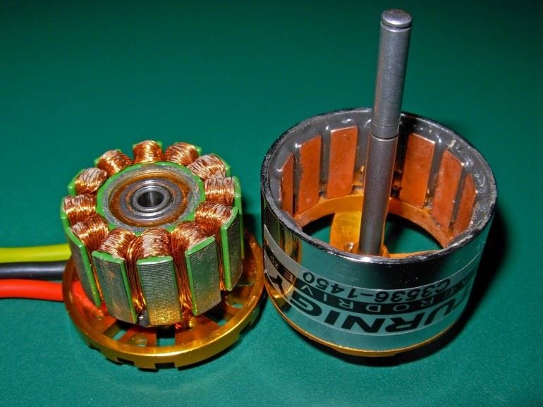 Outrunner Brushless Motor: (Left) Stator,
(Right) permanent magnets fixed to the bell
This setup was tested with various APC electric propellers with worst case scenario conditions. The motor was mounted onto a common adapter mount and then mounted to a bench top. The only place for air to flow was down from the ceiling and then compressed onto a bench top. This could be referred to as an abuse test. Conditions would be more favorable if air were allowed to freely flow as if it was mounted on an airframe, but this placed the most load possible on this setup. By testing the setup in a worst case scenario, we know that it is not possible to achieve any less favorable results or put any more strain on the system.
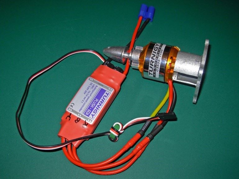 Turnigy Plush 60amp ESC, Turnigy 35-36c motor,
T-28 motor mount
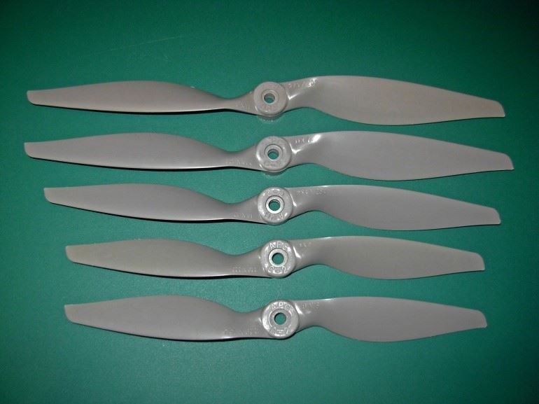 APC Electric Props top to bottom: 11x8, 11x7, 10x10, 9x9, 9x6
When gathering data for this setup each propeller was run at full throttle for 20 seconds before data was recorded. This was done to eliminate any peak performance data that would come from a short burst at full throttle. This would allow time for battery voltage to settle or stabilize under full load. The test was performed with two 2200mAh 3-cell 40c LiPo batteries with a full charge switched halfway through the test.
Results are listed in this table:
|
Propeller
|
kV
|
Amps
|
Volts
|
Watts
|
RPM
|
Pitch Speed
|
Min. Flight
|
Efficiency
|
|
9x6
|
860
|
30
|
11.0
|
330
|
9460
|
53.8 mph
|
4:23
|
76.8%
|
|
9x9
|
810
|
42
|
10.7
|
449
|
8670
|
73.9 mph
|
3:08
|
72.3%
|
|
10x10
|
760
|
48
|
10.6
|
509
|
8060
|
76.3 mph
|
2:44
|
67.9%
|
|
11x7
|
800
|
45
|
10.7
|
482
|
8560
|
56.7 mph
|
3:00
|
71.4%
|
|
11x8
|
780
|
47
|
10.6
|
498
|
8270
|
62.7 mph
|
2:48
|
69.6%
|
|
No Prop
|
1120
|
3
|
|
|
|
|
|
|
|
Test Performed with 2200mAh 40c 3-cell LiPo Battery and 60A ESC
|
|
Static thrust should be considered for propeller selection (not measured in test above)
|
This information is used when selecting the right propeller for the application. The props tested are just ones that I had laying around. Prop selection has several factors to be considered: Battery life/amp draw, speed, and thrust. I did not test thrust on this trial. Generally lower pitch number equals higher thrust. For a 3d model you will want a quick spooling propeller with a large diameter and low pitch number. For an all-out speed plane you want the largest pitch number with the smallest diameter, but thrust is still needed to overcome drag. An aerobatic or sport propeller will fall right in the middle of the 3d and speed planes. In the table above you will notice that the 9x6 and 11x7 props produce about the same pitch speed. The 9x6 will have a longer battery life, but will have less thrust due to a smaller diameter. The 9x9 and 10x10 props produce about the same pitch speed, but the 10x10 is going to use up the battery a lot faster. (Yes, the props were probably stalled in the test. Yes, they will likely unload a lot in the air.) After all the bench testing is complete and you know that the propulsion system will not be harmed when flying, fine tune your prop selection to fit your flying style.
To get a little deeper into the test, a lab scope was utilized with a low amp probe to get a picture of what the ESC was doing to make the motor turn. The images captured were with the APC 9x6 prop. Measurements were made at the battery and not off of one of the 3 legs of the brushless motor. The battery was at 50% at the start of the test and is why the highest average amp draw is lower than what is stated in the table.
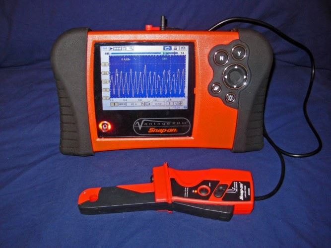 Lab Scope with Low amp probe
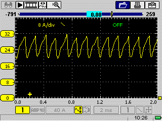
The above screen shot is at 1/3 throttle. Notice that the amperage spikes are at 24 amps. The watt meter read only 12 amps. This is because the average draw was 12 amps, but we know that the system was actually seeing spikes of 24 amps. In the test data in the table we saw an amp draw of 30 amps at full throttle!!!!!
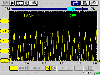
Let’s take a look at ½ throttle:
At half throttle we see an occasional spike of 31 amps and an average amp draw of about 25 amps. Notice how the graph has rose up off of zero and there is always some draw. This is to overcome electromagnetic induction from the stator poles that are not energized.
Let’s explore electromagnetic induction. Any time a magnet passes a coil of wire it tugs on the electrons and generates electricity. This is how a generator produces electricity. By spinning an electric motor you are moving magnets past coils of wire generating electricity. The faster the motor is spun, the more electricity is generated. This is where we get the maximum RPM of our brushless motors in a no load situation.
Once the electromagnetic induction creates a voltage equal to the input voltage, the motor cannot be turned any faster (in our motors) (there are a few exceptions out there but it involves weakening the magnetic fields…) This is why the motors reach maximum RPM at no load when they have not maxed out the switching rate of the ESC.
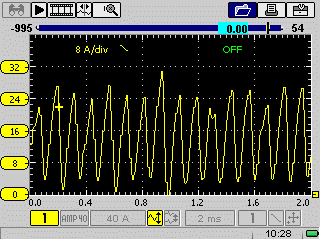
Let’s take a look at full throttle:
Full throttle looks different than all of the other screen shots. Again this is to overcome greater electromagnetic induction due to higher RPMs. Notice that there are no less than 20 amps being drawn and peaks reaching about 32amps. Average amp draw is about 27 amps.
Since we have looked at the screen shots we can now see that amp draw spikes are generally the same between all throttle positions. The frequency of the spikes and the amperage required to overcome the electromagnetic induction is all that is fluctuating. This is essential information that needs to be considered when choosing an ESC. You are always seeing amperage spikes of close to peak amperage draw at even low throttle settings. This is not apparent when using a watt meter that only gives you the average amperage draw.
Say you choose an under rated ESC, in this case we’ll say 20A rating and plan to set the transmitter to a maximum of 80% of the throttle travel so the watt meter never went above 20 amps. You might think that you were not hurting the ESC. You fly it a couple of times and everything is OK. Over time these amperage spikes damage the chips in the ESC and send you favorite airplane in for an “unplanned landing.” You are puzzled…. Your ESC is fried but the watt meter never showed amperage above the 20A rating.
So what killed it? The amperage spikes deteriorated the chips eventually causing them to fail. The same way they would have failed with 100% throttle, but took a little more time. To prevent this from happening choose your prop and ESC from full throttle readings on you watt meter while using a fully charged flight battery for that particular airplane.
This also is a factor when choosing batteries, some batteries have two different discharge ratings depending if it is a pulsed draw or a constant draw. Our brushless motors are definitely a pulsed discharge.
Now that you know what is happening behind the scenes, you should be able to setup more reliable, longer lasting propulsion systems. For any of you that were thrown for a loop with this stuff, feel free to email Jonathon Henrickson at slrcfa.rotate@gmail.com.